
Link aggregation is the networking method that merges multiple physical Ethernet links into a single logical connection to increase bandwidth and deliver built-in redundancy. Governed by IEEE 802.3ad (also known as 802.1AX), this technology is the standard approach for scaling network capacity without replacing existing hardware. Whether you manage a server room, run a growing business, or simply want to understand what your IT team is talking about, link aggregation explained clearly can save you real money and prevent costly downtime.
What is link aggregation and how does it work?
Link aggregation is a Layer 2 technology that combines multiple physical Ethernet links into one logical connection, increasing both bandwidth and resilience. The combined group of physical ports is called a Link Aggregation Group, or LAG. To the network devices above it, a LAG appears as a single, high-capacity interface. This abstraction makes the technology transparent to IP routing, applications, and end users.
The protocol that manages this grouping dynamically is the Link Aggregation Control Protocol, or LACP. Defined under IEEE 802.3ad, LACP supports up to 8 ports per aggregation group and continuously exchanges control frames between connected devices to verify link health and detect misconfigurations. This ongoing negotiation is what separates LACP from older static configurations.

Traffic distribution across member links happens through hashing algorithms. The switch calculates a hash value based on packet attributes, such as source MAC address, destination IP, or TCP port number, and assigns each flow to a specific physical link. This means different conversations between different devices travel across different links simultaneously, spreading the load.
Fault tolerance is one of the most practical advantages. When a member link fails, recovery happens within milliseconds, and traffic automatically redistributes across the remaining active links. For businesses running real-time applications like VoIP or video conferencing, that speed of recovery is the difference between a minor blip and a dropped call.
Key components of a working LAG setup include:
- Physical ports: All member ports must run at the same speed and duplex setting.
- LACP mode: Both ends of the connection should run in active mode for continuous health monitoring.
- Hashing algorithm: Configured at the switch level to match your traffic patterns.
- Compatible hardware: Both connected devices (switches, servers, NAS units) must support LAG.
Pro Tip: Set both ends of your LAG to LACP active mode rather than passive. Active mode devices continuously send control frames, which means misconfigurations get caught before they cause packet loss.
What load balancing methods does link aggregation use?
Understanding link aggregation techniques requires a clear look at how traffic is actually distributed. The hashing algorithm your switch uses determines how effectively your aggregated bandwidth gets utilized across real-world traffic.
The most common load balancing algorithms are:
- Round-robin: Distributes packets evenly across all member links in sequence. Simple but can cause packet reordering.
- Source MAC hash: Routes traffic based on the source MAC address. Works well when many different devices communicate through the switch.
- Source/destination IP hash: Uses both source and destination IP addresses to calculate the link assignment. This is the most common choice for mixed traffic environments.
- Port-based hashing: Uses TCP/UDP port numbers in the hash, offering finer granularity for servers handling many simultaneous connections.
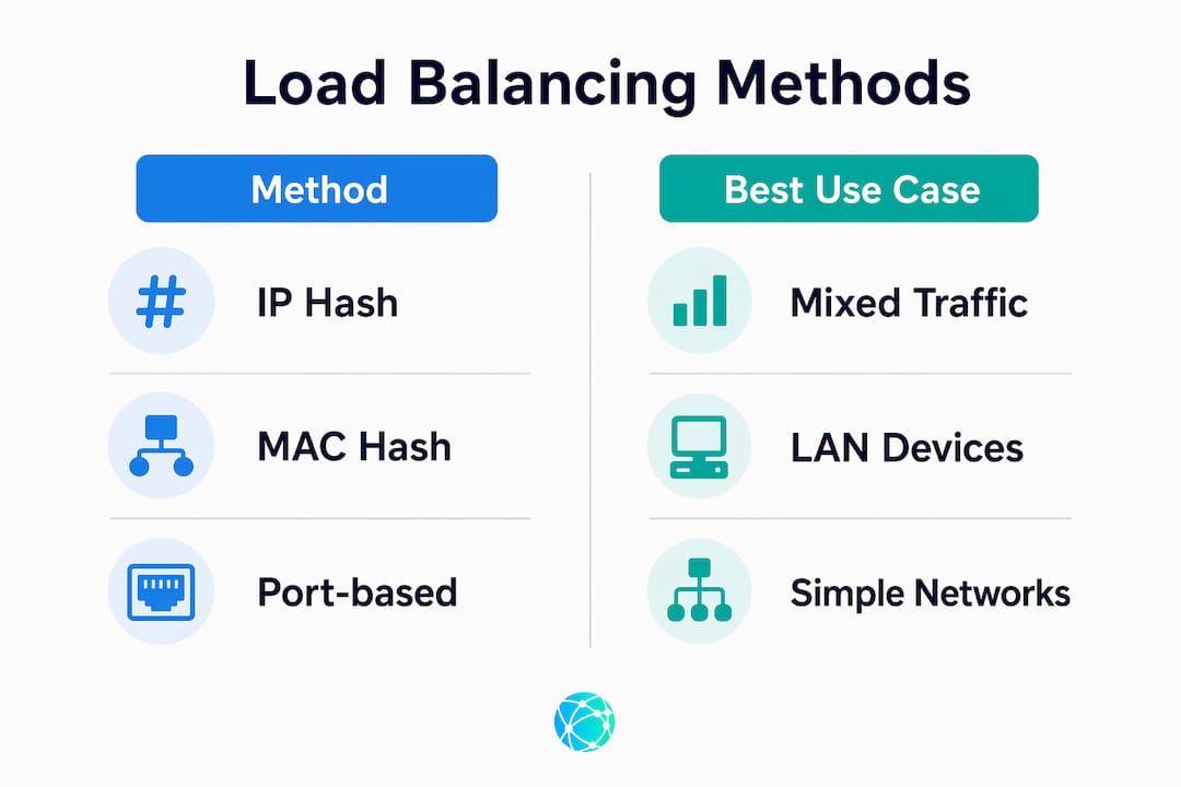
Here is a practical comparison of the two most widely deployed methods:
| Method | Best use case | Limitation |
|---|---|---|
| Source/destination IP hash | Mixed client-server traffic | Poor distribution with few IP pairs |
| Source MAC hash | Access layer with many endpoints | Less effective on routed networks |
| Port-based hash | High-connection-count servers | Requires switch support |
| Round-robin | Packet-level balancing | Risk of out-of-order delivery |
The most critical misconception about link aggregation is the single-session speed limit. A 2x1Gbps LAG allows two simultaneous 1Gbps sessions but caps any single session at 1Gbps. A single file transfer between two specific IP addresses will never exceed the bandwidth of one physical link, regardless of how many links are in the group. This matters enormously when evaluating whether link aggregation solves your specific bottleneck.
Load balancing effectiveness depends heavily on the hashing algorithm and traffic patterns, which means the same hardware can perform very differently depending on configuration choices. A network with only two servers talking to each other will see almost no benefit from aggregation, while a busy office switch serving 50 workstations will see near-linear bandwidth gains.
Pro Tip: Before choosing a hashing algorithm, run a traffic analysis using tools like Wireshark or your switch's built-in flow statistics. Matching the algorithm to your actual traffic profile is the single biggest factor in real-world performance gains.
How does link aggregation compare to channel bonding and SD-WAN?
Link aggregation is strictly a LAN technology operating at Layer 2. It works between two directly connected devices on the same local network, such as a switch connected to a server or two switches connected to each other. It does not extend across the internet or between geographically separate sites.
Channel bonding and SD-WAN operate at the WAN level, combining multiple internet circuits from different ISPs into a single logical connection. Where link aggregation handles traffic between your server and your switch, SD-WAN handles traffic between your office and a cloud data center. The scope, the protocols, and the problems they solve are fundamentally different.
Link aggregation is transparent to higher network layers like IP and to end-user applications. SD-WAN, by contrast, actively manages application-level routing decisions, often using policies based on application type, latency, or packet loss. The two technologies are complementary. A business can run SD-WAN between its offices while simultaneously using link aggregation on the internal switches at each location.
The practical distinction matters when you are diagnosing a performance problem. If your bottleneck is between your file server and your core switch, link aggregation is the right tool. If your bottleneck is your internet connection to AWS or Microsoft Azure, SD-WAN or a circuit upgrade is the answer. Deploying link aggregation to fix a WAN problem will accomplish nothing.
What are the best practices for deploying link aggregation?
Real-world deployment of link aggregation follows a clear sequence that avoids the most common failure modes.
- Audit your hardware first. Confirm that both connected devices support LAG and LACP. Enterprise switches from Cisco, Juniper, and Aruba support it natively. Consumer-grade switches often do not.
- Disconnect member ports before configuring. Configuring active ports on live links without preparation can cause Spanning Tree Protocol conflicts or immediate outages. Always configure the LAG on both ends before reconnecting cables.
- Use LACP active mode on both ends. Active mode devices exchange control frames continuously, catching misconfiguration before it causes packet loss. Passive mode waits for the other side to initiate, which can leave errors undetected.
- Choose your hashing algorithm based on traffic analysis, not defaults. The default algorithm on most switches is source MAC, which performs poorly on routed networks.
- Document every port assignment. When troubleshooting months later, knowing exactly which physical ports belong to which LAG saves hours.
Static LAGs do not detect misconfiguration or link failure automatically, which creates a risk of blackholing where traffic is sent to a failed link and silently dropped. This is the primary reason LACP is the industry standard for any production environment.
From a cost perspective, four aggregated 1Gbps links deliver up to 4Gbps of aggregate capacity across multiple flows, at a fraction of the cost of a 10Gbps switch upgrade. For small and medium businesses managing tight budgets, this is a genuinely practical path to scaling network performance using ports that already exist on current hardware.
One limitation that catches many administrators off guard: link aggregation does not provide device-level redundancy. If the switch itself fails, all member links go down together. Protecting against switch failure requires additional solutions like Multi-Chassis LAG (MC-LAG) or a properly configured Spanning Tree Protocol topology. Understanding this boundary prevents false confidence in a setup that looks redundant but has a single point of failure.
For businesses managing multiple digital touchpoints, the same principle of consolidating connections for efficiency applies online. Learning how to organize multiple links without creating confusion is just as valuable in digital marketing as it is in network engineering.
Key takeaways
Link aggregation delivers real bandwidth gains and fault tolerance only when LACP is configured correctly and the hashing algorithm matches actual traffic patterns.
| Point | Details |
|---|---|
| Core definition | Link aggregation combines multiple physical links into one logical LAG for bandwidth and redundancy. |
| LACP is the standard | IEEE 802.3ad LACP detects failures in milliseconds and prevents misconfiguration blackholing. |
| Single-session speed cap | One session between two endpoints is always limited to one physical link's bandwidth. |
| Cost-effective scaling | Four 1Gbps links aggregate to 4Gbps capacity without expensive hardware replacement. |
| Device redundancy gap | LAG does not protect against switch failure; MC-LAG or STP is required for full redundancy. |
Why most link aggregation deployments underperform
Most networks I have reviewed that use link aggregation are not getting the performance they expect, and the reason is almost always the hashing algorithm. The default setting on most switches is source MAC address, which sounds reasonable until you realize that on a routed network, all traffic from a remote subnet arrives with the same source MAC: the router's interface. Every packet hashes to the same link, and the other links in the group sit idle.
The fix takes about two minutes in the switch CLI. Switching to source/destination IP hash immediately distributes traffic across all member links. But the default is rarely changed because most deployment guides stop at "configure LACP and connect the cables." That gap between documentation and reality is where performance gets lost.
The other issue I see consistently is treating link aggregation as a substitute for proper redundancy planning. A two-link LAG between a server and a switch is not a redundant connection. It is a higher-bandwidth connection with fast failover between links on the same switch. The moment that switch loses power, everything goes down. Businesses that understand this distinction invest in MC-LAG or dual-homed server connections before they need them, not after an outage.
For anyone managing both network infrastructure and digital presence, the logic of consolidation runs through both disciplines. Whether you are growing your audience through a single link hub or aggregating physical ports for bandwidth, the principle is the same: consolidate intelligently, monitor continuously, and know exactly where your single points of failure are.
— Axion
Manage your digital links the way pros manage their networks
The same logic that makes link aggregation powerful in networking applies to your online presence. Spreading your audience across disconnected URLs creates friction and lost engagement. Lflow consolidates every link you need into one branded, mobile-optimized page that takes under two minutes to set up. You get real-time analytics to see exactly which links your audience clicks, a free QR code for offline promotion, and full customization including custom domains, fonts, and color themes. It is the digital equivalent of a well-configured LAG: one clean connection that handles everything. Start for free at Lflow's link in bio tool and see the difference a single, organized hub makes.
FAQ
What is link aggregation in simple terms?
Link aggregation combines two or more physical network cables into one logical connection, increasing total bandwidth and providing automatic failover if one cable fails. It is governed by the IEEE 802.3ad standard using the Link Aggregation Control Protocol (LACP).
Does link aggregation make a single download faster?
No. A single session between two specific endpoints is always limited to the speed of one physical link. A 2x1Gbps LAG caps any single file transfer at 1Gbps; the second link only benefits different simultaneous sessions.
What is the difference between static and dynamic link aggregation?
Static LAG is configured manually with no automatic failure detection, which risks silent packet loss if a link fails. Dynamic LAG uses LACP to continuously monitor link health and automatically remove failed ports from the group.
How many ports can be in a link aggregation group?
Most enterprise-grade switches support up to 8 ports per LAG group under the IEEE 802.3ad standard. All member ports must run at the same speed and duplex setting to function correctly.
Does link aggregation protect against switch failure?
No. Link aggregation only provides redundancy across individual links on the same switch. Protecting against a full switch failure requires Multi-Chassis LAG (MC-LAG) or a Spanning Tree Protocol configuration with a secondary switch.